


The PID Controller is a Proportional – Integral – Derivative controller or three-term controller. It is a control loop mechanism that uses feedback and is widely used in industrial control systems and in a variety of other applications that require constantly configured control. A PID controller continuously calculates an error value e (t) as the difference between a desired setpoint (SetPoint -SP) and the current value of a measurable process variable (Process Variable PV) and applies a correction based on analog, integral and derivative term (denoted by P, I and D respectively), hence the name.
In practice, it automatically applies an accurate and responsive correction to a control function. An everyday example is cruise control in a car, where climbing a hill would reduce speed if there was only constant engine power. The controller PID algorithm restores the measured speed to the desired speed with minimal delay and exceedance by increasing the motor output power in a controlled manner.
Controller operation
The feature of the PID controller is the ability to use the three control terms of analog, integral and derivative influence on the controller output to implement accurate and optimal control. The controller block diagram shown below shows the principles of how these terms are created and applied. Displays a PID controller, which continuously calculates an error value e (t) as the difference between a desired setpoint SP = r (t) and a measured process variable PV = y (t) e (t) = r (t) -y (t) and applies a correction based on a proportional, integral and derivative term. The controller tries to minimize the error over time by adjusting a control variable u (t), such as e.g. opening a control valve,to a new value determined by a weighted sum of the control conditions.
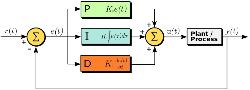
In this model:
The term P is proportional to the current value of the error SP − PV = e (t).
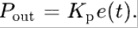
For example, if the error is large and positive, the control output will be proportionally large and positive, taking into account the gain factor K p . Using the analog control only will result in an error between the set point and the actual process value because it requires an error to generate the analog response. If there is no error, there is no corrective answer.
Term I takes into account the previous values of the SP − PV error
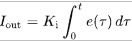
and integrates them over time to produce the term I. For example, if there is a residual error SP − PV after the analog control is applied, the term integral seeks to eliminate the residual error by adding a control result, weight K i , due to the historical cumulative value of the error. When the error is eliminated, the term will stop growing. This will result in a reduction in the analog result as the error decreases, but this is offset by the increasing overall effect.
Term D is the best estimate of the future trend of the SP − PV error,
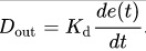
based on its current rate of change. It is sometimes referred to as "prudential control", as it essentially seeks to reduce the effect of the SP − PV error by exerting a control influence created by the rate of change of the error. The faster the change, the greater the effect of control or damping. The role of the constant K d in the calculation of the correction D is important.
Application of PID controller in Code
To implement a PID controller in code or an Arduino program, five parameters must be known:
- proportional constant K p
- integral constant K i
- and derivative constant K d
- entry price (PV)
- and set point value (SP)
The PID calculation must be inside a loop function. The first part of the function should be to determine the time elapsed.
In Arduino, the current time can be determined with the millis () function and the elapsed time is simply:
currentTime = millis ();
elapsedTime = currentTime - previousTime;
Next, the error must be identified:
error = setPoint - input;
Programming on an Arduino simplifies the calculations a lot by using the PID_v1 library. In the example I give you I used the PID_v1 library.
In any case it is necessary to determine the three constants P, I, D. This determination is usually done experimentally and is a laborious process.
Construction
The construction is a continuation of the previous one I did with the two servomotors. After we have added the MPU-9250 sensor to it. See about it here.
The most important thing for the construction is the software that we will write so that the movement in the servomotors is now controlled by the sensor and is done smoothly, without oscillations and brings the system to the desired (horizontal) position.
The construction program for Arduino UNO can be downloaded here.
