


Step Motor
A stepper motor is a type of DC motor that rotates in steps. When an electric current is applied, the motor rotates gradually and the speed of rotation depends on the "speed" at which you apply the electric current to its coils. The direction of rotation depends on the activation sequence of the motor coils. The angle of a step depends on how many windings the motor has.
Step Motor Types
Generally speaking, there are two types of stepper motor, unipolar and bipolar.
Bipolar motors have 4 wires connected to the two separate coils inside the motor - one pair for each coil.
There are also two types of unipolar motor - those with 5 wires and those with 6 wires.
6-wire motors can also be referred to as hybrid motors. They are similar to 4-wire bipolar motors and just have an extra wire connected to the center of each of the coils. If you want to use a 6-wire motor in bipolar mode, just ignore the wires connected to the centers of the coils.
5-wire motors cannot be driven by a driver designed for a bipolar motor. An example of a 5-wire motor, which we develop next, is the small 28BYJ-48 motor that can be seen in many Arduino projects and usually uses a ULN2003 chip as a driver.
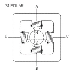
The stepper motor consists of a stator (coils) and a rotor (permanent magnets), see BIPOLAR diagram. The bipolar stepper motor contains independent coils (without being connected to each other by a medium tap), while in the unipolar stepper motor the coils have a medium tap. Usually the two middle taps are connected together and connected to the positive pole of the source. So the bipolar motor has four wires while the unipolar has five.
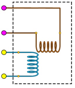
Στον διπολικό κινητήρα για να αναστρέψουμε το μαγνητικό πεδίο του πηνίου πρέπει να αναστρέψουμε την πολικότητα της τάσης στα άκρα του.
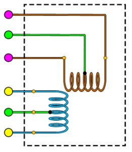
In the unipolar motor if the positive pole of the voltage is applied to the middle tap of the coil, then to reverse the magnetic field of the coil it is sufficient to select the other end of the coil connection for grounding. The circuit is much simpler, but the power of the motor is half, since each step operates half the coil.
Step motor specifications
Data sheets usually list coil current, coil resistance, rated voltage and holding torque, and steps per revolution. For example, for a motor these values are current 1 Amp, resistance 2.7 Ohms, voltage 2.7 Volts, torque 1.4 Kg-cm and 200 steps per revolution.
The nominal voltage is irrelevant for practical purposes. The important element is the rated current.
Rated current is normally the current per coil, and when stepper motor currents are quoted for driver boards, this is usually a value per coil.
Holding torque is the torque available to resist rotation while the motor is stationary. Available torque will decrease as speed increases.
Some manufacturers provide graphs showing how torque varies with speed.
Operating voltage
Stepper motors are very different from regular DC motors.
In a DC motor you control the current to control the speed of the motor. The usual way to control the current is to vary the voltage - perhaps using the Arduino analogWrite() function to control a pulse width modulated current supply to the motor.
Stepper motors almost draw their full current all the time, even when stationary - so they resist moving from their current position. This means they are very inefficient.
For practical purposes, the rated voltage of a stepper motor is irrelevant. It is the voltage that will drive the rated current through the coil when the motor is stationary based on Ohm's law e.g. 2.7v = 1A * 2.7 Ohms. However, once the motor starts moving, the combination of the inductance of the coils and the back-emf created by the motion will prevent the rated voltage from producing the rated current.
For this reason stepper motors usually run at a much higher voltage. This, in turn, means that a specialized stepper motor driver board is needed that can limit the current to what the motor can take. If the current is not limited, the high voltage will quickly destroy the motor.
Related articles on driving various types of stepper motors
https://www.makerguides.com/a4988-stepper-motor-driver-arduino-tutorial/
Control DC motor
In this construction we will drive the motor using a controller and we will measure its speed, as we did in the application "DC Motor - Encoder". To do this we will add another circuit, that of the motor power supply, and a few lines of code to the program we wrote for our previous construction entitled "DC Motor - Encoder".
Secondly we will use an infrared remote control to give driving commands to the engine.
The materials for construction are the same. Here we will focus more on the controller for driving the engine, and we will say a few words about the PWM configuration (Pulse Width Modulation) and how we will implement it in the Arduino UNO.
PWM
The PWM configuration is a periodic square waveform that differs from the percentage of time it is ON or Hight in a period. This ON state is called the Duty Cycle and we measure it as a percentage of the total duration of a period.
In the figure below we see six different forms of a PWM. The green vertical lines determine the duration of a cycle or the number of cycles per unit time.
In the first line we see that the state of the pulses is 0 for the entire duration of their period. Then we say that the Duty Cycle is 0%. In this case the power provided by the pulse is zero.
In the second line a small part of the period, 25% is ON. In this case the power provided by the pulse is 25% of its capacity.
Finally in the last line the pulse is ON throughout its duration and the power it provides is 100% of its capacity.
The Arduino UNO in a very simple way can provide PWM configuration on pins 3, 9, 10, 11 with a frequency of 490 Hz while on pins 5 and 6 with a frequency of 980 Hz. In this application we are not interested in the pulse frequency, we are only interested in the Duty Cycle.
The analogWrite (pin, value) command, which has nothing to do with analog output, generates a PWM pulse on the pin we have defined. The variable value takes values from 0 to 255. For the value 0 it creates a pulse with Duty Cycle 0% and for the value 255 it creates a pulse with Duty Cycle 100%. Thus the value that the variable will have is determined by the relation value = Duty Cycle * 255.
For example to make a pulse with Duty Cycle 20% the value of the variable is value = 0.2 * 255 = 51.

Controllers
The controller we use here is 7A / 160W. It can drive two motors with voltage from 7 to 24V. The following figure shows the interface points of the controller and the following table shows the functions of these interface points.


We use the Label 1.2 points to connect a 12V battery.
Points 3 and 4 to connect the motor power supply (white and red cable)
Point 7 to connect the PWM pulse from the Arduino UNO pin
Points 8 and 9 to connect the IN1 and IN2 select direction as shown in the picture with my notes.
And the + 5V and GND points located before 7 and after 9 as shown in the controller image to connect the power supply to the digital controller circuit.

The following table (Control Logic Table) for the engine we have connected, shows us the movements that the engine will perform depending on the values that will have the inputs IN1 and IN2. You can see their use in the program in the functions goForword () and goBackword ().
Programming
We are now coming to the program that will start our construction.
// Author Manolis Aristovoulidis
// Το πρόγραμμα αυτό κινεί ένα κινητήρα 12V DC με τη χρήση ενός κοντρόλερ
// χρησημοποιεί ένα Infrared τηλεκοντρόλ για να δίνει οδηγίες για την κίνηση
// μετρά και "τυπώνει" την ταχύτητα και την κατεύθυνση της κίνησης.


#include <IRremote.h>

const int RECV_PIN = 12;
IRrecv irrecv(RECV_PIN);
decode_results results;

// Motor A connections
const int enA = 6;
const int in1 = 5;
const int in2 = 4;

//motor A encoder
const byte encoder_pinA = 2;    //A pin -> the interrupt pin 2
const byte encoder_pinB = 10;    //B pin -> the digital pin 10

int pulses;                   //the number of the pulses
boolean Direction;              //the rotation direction

// Set the speed (0 = off and 255 = max speed)
int motorSpeed = 0;


void setup() {
     // Motor control pins are outputs

      Serial.begin(57600);          //Initialize the serial port
      EncoderInit();                //Initialize the module

      pinMode(enA, OUTPUT);
      pinMode(in1, OUTPUT);
      pinMode(in2, OUTPUT);
      irrecv.enableIRIn();
}

void loop() {
    if (irrecv.decode(&results)){
        //Serial.println(results.value, HEX);
        irrecv.resume();

        switch (results.value) {
          case 0xFF18E7:  //key UP
              if(motorSpeed <= 200){
                motorSpeed +=50;
              }
              if(motorSpeed >=0){
                // move forword
                goForword();
              }else{
                //move backword
                goBackword();
              }
          analogWrite(enA, abs(motorSpeed));
          break;

          case 0xFF4AB5:  //key DOWN
              if(motorSpeed > -250){
                motorSpeed -=50;
              }
              if(motorSpeed >=0){
                // move forword
                goForword();
              }else{
                //move backword
                goBackword();
              }
          analogWrite(enA, abs(motorSpeed));
          break;
          case 0xFF38C7:  //key OK
              //stop moving
              stopMove();

          break;
          default:
          // statements
          break;
       }
  }

    Serial.print("Direction:");
      if(Direction){
        Serial.print("Forword   ");
      }else{
        Serial.print("Backword  ");
      }
    Serial.print("Pulses:");
    Serial.println(pulses);
    pulses = 0;
    delay(100);
}

void EncoderInit()
{
  Direction = true;         //default -> Forward
  pinMode(encoder_pinB,INPUT);
  attachInterrupt(digitalPinToInterrupt(encoder_pinA), wheelSpeed, RISING );
}

void wheelSpeed()
{
  int val = digitalRead(encoder_pinB);
  if(val == LOW ){
      Direction = false; //Reverse
      pulses--;
    }else{
      Direction = true;  //Forward
      pulses++;
    }
  }

void goForword(){
    digitalWrite(in1, HIGH);    //1,0 ->Forward
    digitalWrite(in2, LOW);
}

void goBackword(){
    digitalWrite(in1, LOW);    //0,1 ->Backword
    digitalWrite(in2, HIGH);
}

void stopMove(){
    digitalWrite(in1, LOW);    //1,0 ->Forward
    digitalWrite(in2, LOW);
    motorSpeed = 0;
    analogWrite(enA, abs(motorSpeed));
}
In the Loop () of the program there is a switch - case which leads the program according to the command given by the remote control. From the remote control we give three commands, up arrow to increase forward speed, down arrow to reduce speed and finally reverse the movement and finally "OK" to reset the motor speed.
Moving forward is done with the goForword () function
Moving backwards is done with the goBackword () function
The motor is stopped with the stoMove function ()
Finally the speed is defined by the command analogWrite (enA, abs (motorSpeed)) which produces the PWM pulse on the pin enA with Duty Cycle according to the value of the variable motorSpeed.
You can download the program here.
In the video that follows you see the construction in operation. video
What is Servo?
Servo is a general term for a closed loop control system.
A closed loop system uses a feedback signal to adjust the speed and direction of an engine and to achieve the desired result, for example placing the engine in a specific position.
There are servomotors on the market of many types and sizes, here we refer to those used in modeling and robotics. These servomotors also operate on the above principle. They contain a small DC motor connected to the output shaft via the gears, ie a mechanical gearbox, to ensure high torque with a few turns on the servomotor. The output shaft moves an arm that is connected to a potentiometer (pot) which is part of the electronic control circuit (servo driver). The following figure shows the operating diagram of a servomotor.

Schematic diagram of a servomotor
The potentiometer provides position feedback to the control unit where the current position of the motor is compared to the target position.
According to the error, the control unit corrects the actual position of the engine so that it matches the target position.

Internal servomotor
How the servomotor works
In the figure you can see a servomotor. It is connected to three conductors. The GND ground, the 5V voltage which is usually 5 to 7 volts, and the control which is the control signal.

Servo motor connection
You can control the servomotor by sending a series of pulses to the control line. A conventional analog servomotor, such as e.g. the MG995 expects to receive a pulse approximately every 20 milliseconds (ie the signal must be at 50Hz).
The pulse length (Duty Cycle) determines the position of the servomotor. The following figure shows the position of the motor in relation to the control signal.

Servo motor drive
Application
It's time to see how a servomotor connects and works.
You will need some materials:
1. A servomotor e.g. MG995

Servo motor MG995
2. An Arduino UNO board or compatible

Arduino UNO
3. An empty Arduino UNO board on which the connections will be made and then fastened to the Arduino board.

Arduino Sield
4. A 5-7V DC power supply to power the servomotor.
5. A 10K potentiometer
You will also need some tools (soldering iron, etc.), a few meters of thin cable and a little construction experience.
To program and operate the system you must have the Ardouino IDE installed and have little experience with it. Both hardware and software are OPEN, see
https://en.wikipedia.org/wiki/Open_top_material
https://en.wikipedia.org/wiki/Open_Software
Construction
On the blank Arduino UNO board I make the connection circuit of the materials. An example of wiring can be seen at https://www.arduino.cc/en/Tutorial/Knob in which I have made the necessary modifications.
In the photo below you can see the construction is finished. Here I use two servomotors and two potentiometers, because the construction has future use. The servomotors are positioned so that the movements take place in two planes perpendicular to each other. We will use this detail in our next construction.
At the end of your article I have a video where you see the construction in operation.

Each potentiometer has three pins. The two ends are connected to the GND ground and to the 5V respectively. Depending on the rotation position of the potentiometer, the medium will have a potential between 0 and 5V. The middle pin of the potentiometer is connected to the analog input A0 of the Arduino. The values that the program will read for input A0 will be between 0 and 1023.
The servomotive usually needs more power than this can be given by the power supply of the Arduino from a USB port. For this reason we use the additional power supply. The ground of this power supply will be connected to the Arduino GND. It will be good to connect a 1000μF capacitor between the ground and the positive of the power supply, which will ensure the high current requirement when starting the motor.
Servomotors have three cables: current, ground and signal. The power cord is usually red and should be plugged into the 5-7V of the power supply. The ground wire is usually black or brown and should be connected to a ground pin on the Arduino board. The signal pin is usually yellow, orange or white and should be connected to a digital pin on the Arduino board. In our construction it will be connected to the digital pin 4.
Programming
The program I present to you moves two servomotors using two potentiometers as shown in the video. The construction was done with two servomotors because it will be used in the next experiment.
Arduino UNO enables PWM signal generation on pins 3,5,6,9,10 and 11. We use the Servo.h library to simplify programming for PWM signal output, also in the way it handles the library producing PWM signal we can use all digital pins to generate PWM signal.
/*

έλεγχος της θέσης δύο σερβοκινητήρων με τη χρήση δύο μεταβλητών αντιστάσεων – ποτενσιομέτρων

Μανώλης Αριστοβουλίδης 10/2021

*/


#include <Servo.h>


Servo servo1; // δημιουργία ενός servo object για τον έλεγχο του servo

Servo servo2;


int potpin1 = A0; // αναλογικό pin για τη σύνδεση ποτενσιομέτρου

int potpin2 = A1; // αναλογικό pin για τη σύνδεση ποτενσιομέτρου

int val1; // μεταβλητή για την ανάγνωση της τιμής του αναλογικό pin

int val2; // μεταβλητή για την ανάγνωση της τιμής του αναλογικό pin


void setup() {

servo1.attach(4); // κάνει προσάρτηση του servo στο pin 4 του servo object

servo2.attach(5); //κάνει προσάρτηση του servo στο pin 5 του servo object


Serial.begin(9600); //αρχικοποιεί τη σειριακή επικοινωνία

}


void loop() {

val1 = analogRead(potpin1); // διαβάζει την αναλογική τιμή (τιμές μεταξύ 0 και 1023)

val2 = analogRead(potpin2); // διαβάζει την αναλογική τιμή (τιμές μεταξύ 0 και 1023)

val1 = map(val1, 0, 1023, 0, 180); // μεταροπή σε κλίμακα για το servo (τιμές μεταξύ 0 και 180)

val2 = map(val2, 0, 1023, 0, 180); // μεταροπή σε κλίμακα για το servo (τιμές μεταξύ 0 και 180)

servo1.write(val1); // ρυθμίζει τη θέση του servo στην τιμή της κλίμακας

servo2.write(val2); // ρυθμίζει τη θέση του servo στην τιμή της κλίμακας


Serial.print("val1 : ");

Serial.print(val1);

Serial.print(" - val2 : ");

Serial.println(val2);


delay(20); // περιμένει για την ολοκλήρωση της κίνησης του servo

}
The code can be downloaded here http://www.avlos.gr/index.php/el/lipsis/download/16-servo-knob
In the video that follows you can see the mechanism in operation https://youtu.be/BCxv9VGqhQk
Ultrasonic Sensor HC-SR04 and Arduino
In this article we will see how the HC-SR04 ultrasonic sensor works and how to use it with Arduino. This is the most popular sensor for measuring distance. We can use it to build obstacle avoidance robots with Arduino, and that's what we'll be doing next.
Description of the HC-SR04 material
The HC-SR04 is an affordable and easy-to-use distance measurement sensor. It has a range from 2 cm to 400 cm.
The sensor consists of two ultrasonic transducers. One is a transmitter that emits ultrasonic pulses of sound and the other is a receiver that listens to the reflected waves. It's basically a SONAR like the ones submarines use.
In the figure below we see the image of the sensor.
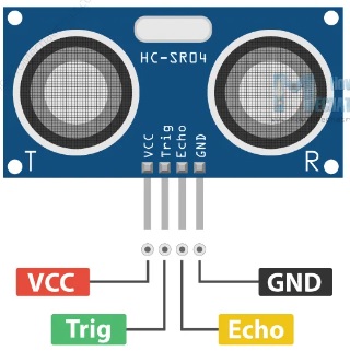
The sensor has 4 pins. VCC and GND go to the 5V and GND pins on the Arduino, and Trig and Echo go to any Arduino digital pin. Using the Trig pin we send the ultrasonic wave from the transmitter and with the Echo pin we receive the reflected signal.
How the HC-SR04 Ultrasonic Distance Sensor Works
As shown in the image below the sensor emits an ultrasound at 40 000 Hz which travels through the air and if there is an object or obstacle in its path it will be reflected back to the unit. By taking into account the travel time and the speed of sound we can calculate the distance.
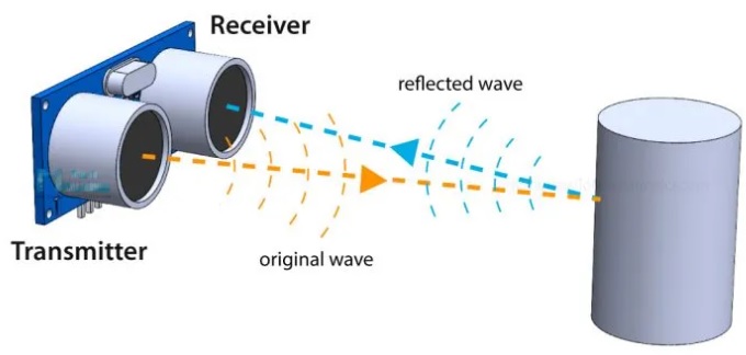
To generate the ultrasound we need to set the Trig pin high for 10 µs. This will send out a group of 8 ultrasound cycles that will travel at the speed of sound. The Echo spike goes up immediately after sending the group of 8 ultrasound cycles and starts listening or waiting for this wave to be reflected by an object.
If there is no object or reflected pulse, the Echo pin will time out after 38 ms and return to the low state.
If we receive a reflected pulse, the Echo pin will fall earlier than this 38ms. Depending on the time the Echo pin was HIGH, we can determine the distance the sound wave traveled, thus the distance from the sensor to the object.
The diagram below shows the function we described.
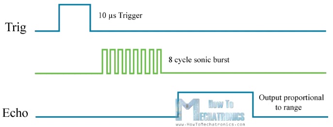
For this purpose we use the following basic formula to calculate the distance:
D = U x T Distance equal speed times time.
We actually know both the speed and time values. Time is the time the Echo pin was HIGH and velocity is the speed of sound which is 340 m/s. There is one extra step we need to do, and that is to divide the final result by 2. We need to do this because we are measuring how long it takes the sound wave to travel to the object and reflect back.
Assume the Echo pin was HIGH for 2 ms. If we want to express the result of the distance in cm, we can convert the value of the speed of sound from 340m/s to 34cm/ms.
So if the Echo pin was HIGH for 2ms (which we measure using the pulseIn() function for the Arduino, the distance from the sensor to the object is 34cm.
D = (U x T) / 2 = (34cm/ms x 2ms) / 2 = 34cm.
How to connect HC-SR04 ultrasonic sensor to Arduino
The connection of the Arduino Uno with the distance sensor is shown in the figure below.
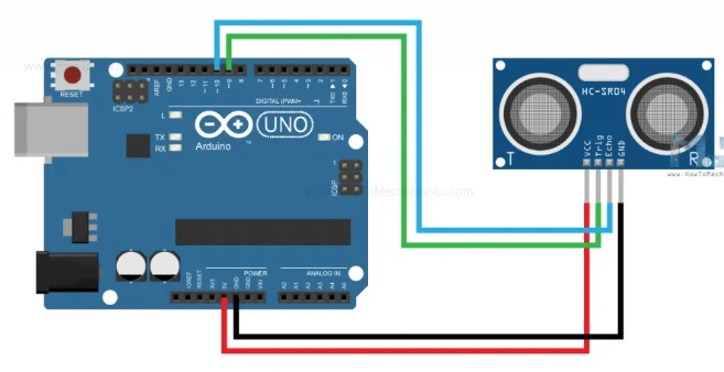
The GRD and VCC pins of the module must be connected to the ground and 5V pins on the Arduino board respectively, and the trig and echo pins to any Digital I/O pin on the Arduino board.
Arduino code for the HC-SR04 ultrasonic sensor
/*
Ultrasonic Sensor HC-SR04 and Arduino Tutorial
by Dejan Nedelkovski,
www.HowToMechatronics.com
*/
// defines pins numbers
const int trigPin = 9;
const int echoPin = 10;
// defines variables
long duration;
int distance;
void setup() {
pinMode(trigPin, OUTPUT); // Sets the trigPin as an Output
pinMode(echoPin, INPUT); // Sets the echoPin as an Input
Serial.begin(9600); // Starts the serial communication
}
void loop() {
// Clears the trigPin
digitalWrite(trigPin, LOW);
delayMicroseconds(2);
// Sets the trigPin on HIGH state for 10 micro seconds
digitalWrite(trigPin, HIGH);
delayMicroseconds(10);
digitalWrite(trigPin, LOW);
// Reads the echoPin, returns the sound wave travel time in microseconds
duration = pulseIn(echoPin, HIGH);
// Calculating the distance
distance = duration * 0.034 / 2;
// Prints the distance on the Serial Monitor
Serial.print("Distance: ");
Serial.println(distance);
delay(500);
}
Explanation of the code
First we need to define the Trig and Echo pins. In this case they are pins number 9 and 10 on the Arduino board and I call them trigPin and echoPin. We need a Long variable called "duration" for the travel time we will get from the sensor and an integer variable for the distance "distance".
// defines pins numbers
const int trigPin = 9;
const int echoPin = 10;
// defines variables
long duration;
long distance;
In the setup we need to set trigPin as output and echoPin as input and also start serial communication to display the results on the screen.
void setup() {
pinMode(trigPin, OUTPUT); // Sets the trigPin as an Output
pinMode(echoPin, INPUT); // Sets the echoPin as an Input
Serial.begin(9600); // Starts the serial communication
}
In the loop() loop we first need to make sure trigPin is clear, so we need to set this pin to LOW state for 2 µs. Now to generate the Ultra sound wave we need to set the trigPin to HIGH state for 10 µs.
// Clears the trigPin
digitalWrite(trigPin, LOW);
delayMicroseconds(2);
// Sets the trigPin on HIGH state for 10 micro seconds
digitalWrite(trigPin, HIGH);
delayMicroseconds(10);
digitalWrite(trigPin, LOW);
Using the pulseIn() function we read the travel time and put that value into the 'duration' variable. This function has 2 parameters, the first is the name of the Echo pin and the second is the state of the pulse we are reading, either High or Low.
// Reads the echoPin, returns the sound wave travel time in microseconds
duration = pulseIn(echoPin, HIGH);
In this case, we need this set to HIGH, as the HC-SR04 sensors set the Echo pin to High after the transmitter sends the 8-cycle ultrasonic burst. This essentially starts the timing and once we receive the reflected sound wave the Echo pin will go Low which stops the timing. Finally the function will return the pulse length in microseconds.
To get the distance we will multiply the duration by 0.034 and divide it by 2 as we explained this equation earlier.
// Reads the echoPin, returns the sound wave travel time in microseconds
duration = pulseIn(echoPin, HIGH);
// Calculating the distance
distance = duration * 0.034 / 2;
Στο τέλος θα εκτυπώσουμε την τιμή της απόστασης στην οθόνη.
The information I quoted I got mainly from the site
https://howtomechatronics.com/tutorials/arduino/ultrasonic-sensor-hc-sr04/
DC motor with encoder
In this article we will make a simple construction to understand the operation of the encoder in a DC motor.
The materials we will need to implement our construction are
- an Arduino Uno ,
- a DC power supply for the motor,
- an engine drive controller ,
- and a DC motor with an encoder adapted to its construction.
- an Arduino UNO Shield, blank perforated board
- some connection materials, thin wires in different colors
All the necessary connections will be made on the blank board. The board wiring I present below is a good guide to construction.
In the photo below you can see the DC motor I chose to use. As you can see it has a built-in encoder. It is up to you whether you want to use it as a simple DC motor or if you want to use the encoder or finally use the motor and the encoder together.

Engine
JGB37-520 DC motor with mechanical gearbox and encoder.
It is mainly used in variable speed cars, self-balancing cars (with two wheels), racing cars, monitoring car, robots and other related constructions.
The speed encoder operates using the Hall effect .
Engine wiring:
1, red: motor power supply + (polarity to white reverses motor drive)
2, black: encoder power supply -
3, yellow: signal line, (A)
4, green: signal line, (B )
5, blue: encoder power supply +
6, white: motor power supply - (alternating polarity with red reverses motor drive)
In our first construction we will use only the engine encoder to understand its operation. As you can see in the image below, the motor power cables, which are Red and White, are not connected. Only the encoder cables are connected. We will rotate the motor shaft by hand and monitor the signals generated.

An encoder works by observing changes in the magnetic field generated by a magnet attached to the motor shaft. Here you will find the principle of operation of the sensor based on the HALL effect .
As the motor rotates the encoder outputs will be activated periodically. When the magnet is rotated clockwise, output "A" will be activated first and when rotated counterclockwise, output "B" will be activated first. This way you know exactly when the motor shaft rotates. This can be very convenient for cases where we need to control the forward or backward movement of a DC motor.
The following diagram shows the phase difference between outputs A and B of the encoder. We will programmatically exploit this phase difference to control the motor movement.

The following figure shows the wiring for two identical engines on an Arduino UNO board. Other equipment will be connected to this board later. We will use in our example only the encoder from one engine.
It can be seen that there are two connectors for each motor, one for Motor A and one for encoder A. In this example we will only use the Encoder A
connector. Four connectors are connected to this connector. The two ends are for powering the encoder, GND and VCC. The two middle ones are connected one to pin D2 and the other to pin D10. Note here that pins D2 and D3 are the only ones used to create interrupts on the Arduino UNO board. We will encounter this when writing the program.

Let's write a very simple program to understand how a coder works and how to read the coder outputs.
To read the encoder, we will connect the encoder output pins to the Arduino terminals 2 and 10. Pin 2 is an interrupt pin. The encoder power cables will be connected to the Arduino 5V and GND.
//Author :  Manolis Aristovoulidis

//Περιστρέφω το μοτέρ με το χέρι και μετράω και τυπώνω
// την ταχύτητα και την κατεύθυνση της κίνησης
//θετικοί αριθμοί συμβολίζουν κίνηση δεξιόστροφη,
//αρνητικοί αριθμοί συμβολίζουν αριστερόστροφη κίνηση

const byte encoder_pinA = 2;    //A pin -> the interrupt pin 2
const byte encoder_pinB = 10;    //B pin -> the digital pin 10

int pulses;                   //the number of the pulses
boolean Direction;              //the rotation direction


void setup()
{
  Serial.begin(57600);          //Initialize the serial port
  EncoderInit();                //Initialize the module
}

void loop()
{
  Serial.print("Direction:");
  if(Direction){
    Serial.print("Forword   ");
  }else{
    Serial.print("Backword  ");
  }
  Serial.print("Pulses:");
  Serial.println(pulses);
  pulses = 0;
  delay(100);
}

void EncoderInit()
{
  Direction = true;         //default -> Forward
  pinMode(encoder_pinB,INPUT);
  attachInterrupt(digitalPinToInterrupt(encoder_pinA), wheelSpeed, RISING );
}

void wheelSpeed()
{
  int val = digitalRead(encoder_pinB);
  if(val == LOW ){
      Direction = false; //Reverse
      pulses--;
    }else{
      Direction = true;  //Forward
      pulses++;
    }
  }
In the monitoring of the serial port we observe the following results.
From here you can download the program for the construction
Direction:Forword   Pulses:0
Direction:Forword   Pulses:0
Direction:Forword   Pulses:0
Direction:Forword   Pulses:3
Direction:Forword   Pulses:17
Direction:Forword   Pulses:38
Direction:Forword   Pulses:63
Direction:Forword   Pulses:85
Direction:Forword   Pulses:102
Direction:Forword   Pulses:112
Direction:Forword   Pulses:117
Direction:Forword   Pulses:112
Direction:Forword   Pulses:98
Direction:Forword   Pulses:86
Direction:Forword   Pulses:74
Direction:Forword   Pulses:64
Direction:Forword   Pulses:53
Direction:Forword   Pulses:42
Direction:Forword   Pulses:33
Direction:Forword   Pulses:25
Direction:Forword   Pulses:17
Direction:Forword   Pulses:8
Direction:Forword   Pulses:0
Direction:Backword  Pulses:-3
Direction:Backword  Pulses:-17
Direction:Backword  Pulses:-39
Direction:Backword  Pulses:-54
Direction:Backword  Pulses:-67
Direction:Backword  Pulses:-79
Direction:Backword  Pulses:-88
Direction:Backword  Pulses:-92
Direction:Backword  Pulses:-97
Direction:Backword  Pulses:-89
Direction:Backword  Pulses:-77
Direction:Backword  Pulses:-66
Direction:Backword  Pulses:-56
Direction:Backword  Pulses:-45
Direction:Backword  Pulses:-35
Direction:Backword  Pulses:-27
Direction:Backword  Pulses:-19
Direction:Backword  Pulses:-12
Direction:Backword  Pulses:-6
Direction:Backword  Pulses:0
Direction:Backword  Pulses:0
Direction:Backword  Pulses:0
When it starts the program correlates the wheelSpeed () function with the interrupt that will occur in pin 2.
This interrupt will occur whenever the pulse in pin 2 rises (from 0 to 5V) whereupon the wheelSpeed () function will be executed. The signal line A of the encoder is connected to pin 2.
The first thing the wheelSpeed () function does is read the value of pin 10, ie the signal line B of the encoder. If its value is 0 (LOW) it means that the signal A precedes the B, that is, the movement is forward. At the same time it increases the value of the pulses by one unit.
In the other case where B precedes A the Direction variable becomes false and the pulse value decreases by one unit. For this reason we have negative values for the pulses when the motion is reversed.
The loop executed by the program (ie the loop function) every 100 msec sends the direction and pulse values to the serial port and resets the pulses.
So as we turn the engine by hand, the values we see in the table below are generated. These are snapshots of the engine condition per 100 msec.
The PID Controller is a Proportional – Integral – Derivative controller or three-term controller. It is a control loop mechanism that uses feedback and is widely used in industrial control systems and in a variety of other applications that require constantly configured control. A PID controller continuously calculates an error value e (t) as the difference between a desired setpoint (SetPoint -SP) and the current value of a measurable process variable (Process Variable PV) and applies a correction based on analog, integral and derivative term (denoted by P, I and D respectively), hence the name.
In practice, it automatically applies an accurate and responsive correction to a control function. An everyday example is cruise control in a car, where climbing a hill would reduce speed if there was only constant engine power. The controller PID algorithm restores the measured speed to the desired speed with minimal delay and exceedance by increasing the motor output power in a controlled manner.
Controller operation
The feature of the PID controller is the ability to use the three control terms of analog, integral and derivative influence on the controller output to implement accurate and optimal control. The controller block diagram shown below shows the principles of how these terms are created and applied. Displays a PID controller, which continuously calculates an error value e (t) as the difference between a desired setpoint SP = r (t) and a measured process variable PV = y (t) e (t) = r (t) -y (t) and applies a correction based on a proportional, integral and derivative term. The controller tries to minimize the error over time by adjusting a control variable u (t), such as e.g. opening a control valve,to a new value determined by a weighted sum of the control conditions.
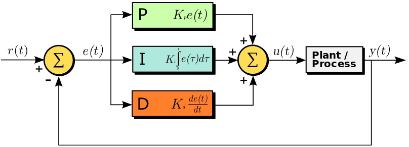
In this model:
The term P is proportional to the current value of the error SP − PV = e (t).
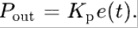
For example, if the error is large and positive, the control output will be proportionally large and positive, taking into account the gain factor K p . Using the analog control only will result in an error between the set point and the actual process value because it requires an error to generate the analog response. If there is no error, there is no corrective answer.
Term I takes into account the previous values of the SP − PV error
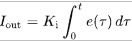
and integrates them over time to produce the term I. For example, if there is a residual error SP − PV after the analog control is applied, the term integral seeks to eliminate the residual error by adding a control result, weight K i , due to the historical cumulative value of the error. When the error is eliminated, the term will stop growing. This will result in a reduction in the analog result as the error decreases, but this is offset by the increasing overall effect.
Term D is the best estimate of the future trend of the SP − PV error,
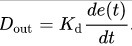
based on its current rate of change. It is sometimes referred to as "prudential control", as it essentially seeks to reduce the effect of the SP − PV error by exerting a control influence created by the rate of change of the error. The faster the change, the greater the effect of control or damping. The role of the constant K d in the calculation of the correction D is important.
Application of PID controller in Code
To implement a PID controller in code or an Arduino program, five parameters must be known:
- proportional constant K p
- integral constant K i
- and derivative constant K d
- entry price (PV)
- and set point value (SP)
The PID calculation must be inside a loop function. The first part of the function should be to determine the time elapsed.
In Arduino, the current time can be determined with the millis () function and the elapsed time is simply:
currentTime = millis ();
elapsedTime = currentTime - previousTime;
Next, the error must be identified:
error = setPoint - input;
Programming on an Arduino simplifies the calculations a lot by using the PID_v1 library. In the example I give you I used the PID_v1 library.
In any case it is necessary to determine the three constants P, I, D. This determination is usually done experimentally and is a laborious process.
Construction
The construction is a continuation of the previous one I did with the two servomotors. After we have added the MPU-9250 sensor to it. See about it here.
The most important thing for the construction is the software that we will write so that the movement in the servomotors is now controlled by the sensor and is done smoothly, without oscillations and brings the system to the desired (horizontal) position.
The construction program for Arduino UNO can be downloaded here.
Motion is the constant change of the position of an object in space. Here I will introduce you in simple words the 9-axis sensor that monitors the change of its position in the three-dimensional space, the MPU 9250.
Then I will present you a simple construction with the MPU 9250 sensor based on the construction I made with the servomotors.
The position sensor can be used in aircraft (various drones and quadcopters), smartphones and robotics, in various operations and in devices related to 3D control and motion recognition.
The MPU-9250 is a System in Package (SiP) that combines two chips: the three-axis MPU-6500 gyroscope, which is also a three-axis accelerometer, and the AK8963, which is a three-axis magnetometer. So the MPU 9250 performs the functions of several sensors at the same time: it is a gyroscope, accelerometer and magnetometer.
Let us dwell a little on each of them.
The gyroscope is a sensor that responds to changes in the orientation angles in space. In the drone, it is used to stabilize the position of the device in the air and protect it from the wind.
The accelerometer compares the acceleration projection of an object to the acceleration of gravity and is able to measure the linear velocity of the object and, together with the gyroscope, its position in space.
A magnetometer is a device for measuring the intensity of the nearest magnetic field acting on an object (the name of the sensor speaks for itself).
According to some sources, the MPU 9250 is the smallest nine-axis sensor in the world. This indicates the high performance of the chip, which is provided using CMOS MEMS ( microelectromechanical systems ) technology.
The case of the unit consists of two smaller crystals, one of which is responsible for the gyroscope and accelerometer and the other for the magnetometer. The data from these crystals are processed by the integrated signal processor DMP (Data Management Platform) using Motion Fusion algorithms and transmitted via the I 2 C or SPI interfaces .
In addition to high performance, the unit is quite popular among electrical engineers and those who love remote control devices, while also having low power consumption and cost.

Principle of operation of the accelerometer
An accelerometer measures the rate at which the speed of an object changes over time, also known as acceleration. With an accelerometer, you can also understand the angle of inclination of the sensor relative to the ground.
An accelerometer has tiny crystals that are pressurized when vibrations occur. From this pressure, a voltage is generated that gives an indication of any acceleration. The unit of measurement for acceleration is the measure per second squared (m / s ^ 2). But as the accelerometer sensors express measurements in "g", a "g" is the value of the earth's gravity equal to 9.8 meters per second squared.

For example, in a 3-axis accelerometer such as the MPU9250 accelerometer sensor, when mounted horizontally with the Z axis up, the output of the sensor Z axis = 1 g or 9.8m / s 2 while X and Y = 0 This is due to the force of gravity perpendicular to the X and Y axes and thus does not affect them.
From this data, with simple trigonometric mathematics, one can calculate the angle of the sensor and consequently the construction on which the sensor is attached.
Principle of gyroscope operation
The gyroscope measures the speed of rotation or the rate of change of angular position over time. Its operation is based on the Coriolis effect.
When a mass moves in a certain direction at a certain speed and an external angular rotation rate is applied, then a force will be detected which the sensor will detect.
The gyroscope outputs are in degrees per second
If we know the initial angle of the IMU, we can add the value given to us by the gyroscope to know the new angle at any time. Suppose we start the IMU from 0 °. If the instrument gives us a measurement every second and marks 3 on the X axis, we will have the angle with this simple formula:
AngleX = PreviousAngleX + GyroDataX * elapsedTime
AngleY = PreviousAngleY + GyroDataY * elapsedTime
Where elapsedTime is the time elapsed each time this formula is calculated within the loop, PreviousAngle is the angle calculated the last time this formula was called and GyroData is the y or X angle reading of the gyroscope.
The magnetometer
The MPU-9250 chip includes the AK8963 which is the magnetometer. This may know the orientation relative to the magnetic north, similar to how a hand compass works. Built-in 16-bit ADCs simultaneously sample the 3 drive axles (X, Y, Z).
The magnetometer can be calibrated automatically using the magcalMPU9250 function (float * dest1, float * dest2) and calibrates the magnetometer as you move the sensor in figure eight. Saves the maximum and minimum readings and takes the average.
Construction
The construction is a continuation of the previous one I did with the two servomotors . To this we will add the MPU-9250 sensor. The most important thing for the construction is the software that we will write so that the movement in the servomotors is now controlled by the sensor and not by the potentiometers.
The following figure shows the connection circuit of the sensor with the Arduino UNO.

The connection is made with the I2C (Inter-Integrated Circuit) bus, a communication protocol with two conductors that the sensor has.
For the sake of simplicity I will use three of the nine axes of the sensor. I will only use the accelerometer for the x, y and z axes. The drive will be in two levels perpendicular to each other and will be provided by the two servomotors. As you can see on the sensor board the manufacturer has marked the axes. The axes are parallel to the planes of motion, each with a plane of motion.
The purpose of the construction is to keep the sensor in a horizontal plane as well as to turn the support level of the construction.
The sensor is mounted on a stand that is horizontal at rest. We place it so that it is parallel to the support base. Then as I rotate the stand I will notice how the servomotors bring the sensor to a horizontal position.
From the basket with my grandchildren's toys I took a smurf, Spirtoulis, and put it on the platform with the sensor. Spirtoulis' upright posture immediately indicates that the sensor is horizontal.
The photo below shows the construction and the video I give you at the end of the article shows the operation of the construction.

Programming
My advice is that the libraries you use for the Arduino IDE are in the folder of the project you are working on. The library I used for the MPU9250 is the Bolder_Flight_Systems_MPU9250 which if you do not have it installed is easy to download from the internet.
Then I quote the code I wrote which you can download from here
//Author : Manolis Aristovoulidis
//Το πρόγραμμα αυτό χρησιμοποιεί ένα MPU-9250 και δύο σερβοκινητήρες
//με τη λειτουργία του προγράμματος οισερβοκινητήρες κρατουν πάντα σε
//οριζόντια θέση τον αισθητήρα


#include <Wire.h>
#include <MPU9250.h>
#include <Servo.h>


Servo servo_x;  // δημιουργία ενός servo object για τον έλεγχο του servo
Servo servo_y;

int val_x = 95;     // μεταβλητή για την γωνια κίνησης του servo_x
int val_y = 100;    // μεταβλητή για την γωνια κίνησης του servo_y

 // an MPU9250 object with the MPU-9250 sensor on I2C bus 0 with address 0x68
 MPU9250 IMU(Wire,0x68);


int status;

 //Acc Variables

float rad_to_deg = 180/3.141592654;           //This value is for pasing from radians to degrees values
float Acc_rawX, Acc_rawY, Acc_rawZ;           //Here we store the raw data read
float Acc_angle_x, Acc_angle_y;               //Here we store the angle value obtained with Acc data

float Total_angle_x, Total_angle_y;           //Here we store the final total angle

int x_tilt = 0;
int y_tilt = 0;
int i;


void setup() {
  // serial to display data
  Serial.begin(115200);
  while(!Serial) {}

  servo_x.attach(4);    //κάνει προσάρτηση του servo στο pin 4 του servo object
  servo_y.attach(5);    //κάνει προσάρτηση του servo στο pin 5 του servo object

  //περιστοφή των σερβοκινητήρων
  servo_x.write(val_x);   //Μετά από πειραματισμούς αυτή είναι η
  servo_y.write(val_y);   //οριζόντια θέση για τη βάση του MPU9250

  delay(1000);

  // start communication with IMU
  status = IMU.begin();
  if (status < 0) {
    Serial.println("IMU initialization unsuccessful");
    Serial.println("Check IMU wiring or try cycling power");
    Serial.print("Status: ");
    Serial.println(status);
    while(1) {}
  }
  /* Default values of MPU9250
   * accel range to 16G as default
   * gyro range to 2000DPS as default
   * bandwidth to 184Hz as default
   * sample rate divider to 0 as default
   *
   */
   // αναμονή για το calibration που προκαλει η IMU.begin()
  delay(3000);
}

void loop() {

  IMU.readSensor();
  Acc_rawX = IMU.getAccelX_mss();
  Acc_rawY = IMU.getAccelY_mss();
  Acc_rawZ = IMU.getAccelZ_mss();


  /*---Y---*/
  Acc_angle_x = (atan((Acc_rawY)/sqrt(pow((Acc_rawX),2) + pow((Acc_rawZ),2)))*rad_to_deg) ;
  /*---Y---*/
  Acc_angle_y = (atan(-1*(Acc_rawX)/sqrt(pow((Acc_rawY),2) + pow((Acc_rawZ),2)))*rad_to_deg) ;


////////////////////////////////////// Γωνία κλίσης και φίλτρο /////////////////////////////////////


  Total_angle_x = 0.94 *Total_angle_x  + 0.06*Acc_angle_x;
  Total_angle_y = 0.94 *Total_angle_y  + 0.06*Acc_angle_y;

  x_tilt = (int)Total_angle_x ;
  y_tilt = (int)Total_angle_y ;

//********************* Υπολογισμός κίνηση επαναφοράς στον άξονα των Χ **************************************
  if(x_tilt > 1){
    val_x--;
  }
  if(x_tilt < -1){
    val_x++;
  }
  if(val_x > 180){val_x = 180;}
  if(val_x < 0){val_x = 0;}
//********************* Υπολογισμός κίνηση επαναφοράς στον άξονα των Υ ****************************************
  if(y_tilt > 1){
    val_y++;
  }
  if(y_tilt < -1){
    val_y--;
  }
  if(val_y > 180){val_y = 180;}
  if(val_y < 0){val_y = 0;}

//******************* Κίνηση των σερβοκινητήρων σε γωνία μεταξύ 0-180 μοιρών ******************************************

  servo_x.write(val_x);   // ρυθμίζει τη θέση του servo στην τιμή της κλίμακας
  servo_y.write(val_y);   // ρυθμίζει τη θέση του servo στην τιμή της κλίμακας

  delay(50);
}
By using two servomotors, the platform that supports the MPU9250 motion sensor is always kept in a horizontal position. No matter how I turn the base on which the whole mechanism rests, the platform returns to a horizontal position.
In the image below you can see the values given by the accelerometer of the sensor while moving, while trying to balance the value to zero for the x-axis. The red line shows the sensor values and the green line shows the values given by the smoothing filter on line 166 of the program and which values drive the servomotor x.

Construction in operation is shown here .
DC motor
There are different types of motors used in small and medium sized robotics projects. These can generally be classified into categories
- Step motors
- Servo motors
- DC motors
They come in a wide variety of sizes and capabilities and are used in different sized applications.
Stepper motors and servomotors are designed in such a way that we can control their position. We can control the steps forward and backward.
Servo motors can generally be moved from 0 to 180 degrees. Therefore you can move your motor in any position between 0 and 180. Similarly, in stepper motors, you can control the steps accurately. This is why stepper motors are used in CNC machines, 3D printers, etc.
Here we will deal with direct current motors (DC motors). DC motors are often used in robotics applications and are quite different from stepper motors and servomotors.
So these three types of engines have different construction and different purpose of use.
When a DC motor is started, it immediately starts to spin, and spins continuously. You can not exactly check its position without using a specific technique. Again you can not 100% control its position in a DC motor as you do with the Stepper motor and Servo. But if you add an encoder to the continuous engine then it really changes the whole game. By adding an encoder, you can track the engine speed, distance traveled and thus create a nice feedback system that can be used to control the DC motor. You can then stop the DC motor in the position where you want it to stop.Note here that the reversal of polarity in the motor power supply causes it to move in the opposite direction.
Using a coder to control the DC motor is not such a simple matter. You can not just start adding a codec to the DC motor to start controlling it. To use an encoder you will need a controller, and a program that will guide the controller. The controller will read the encoder and then test the DC motor accordingly according to the pre-defined instructions written by the programmer.
The speed of rotation of the DC motor is usually controlled by supplying it with a PWM (Pulse-width modulation) waveform. A PWM waveform, as shown in the following figure, is actually a periodic waveform that has two parts. The ON part in which the waveform has its maximum value and the OFF part in which it has the value zero. The ON segment is called the Duty Cycle and is measured in either time units (ms, us, etc.) or as a percentage (%) over the period (Period).

By applying a PWM waveform to the power supply of a load we manage to control the percentage of power that falls on the load. In case the load is an engine this implies control of the engine speed. In the figure below you can see such a DC motor power connection.

Control DC motor with encoder:
Beginners in microcontroller programming are usually more comfortable using the Arduino Uno or Arduino mega or Arduino Nano. For this reason in the constructions - examples I will use the Arduino Uno. You can try the same programs on both Arduino Nano and Arduino Mega.
To get started, you will need:
- an Arduino Uno ,
- a DC power supply for the motor,
- an engine drive controller ,
- and a DC motor with an encoder adapted to its construction.
The steps we will follow will be the following.
- We will first get acquainted with the use of the encoder by moving the motor manually.
- We will then power the engine using a controller to control the direction of movement and its speed.
